This is why UML diagrams are included in many code training and software documentation. Although they might take quite a while to build, the results make it easy for developers to understand the software quickly without wasting time in frequent meetings. Suppose your business revolves around software development and design. In that case, UML diagrams can be of massive help to your team to document the ideas visually and make the development process a bit simpler. But what are these UML diagrams exactly? In this article, I’ll discuss UML diagrams, how they can help you, their usage, and some tools to create these diagrams with ease. Ready? Let’s go in!
What is a UML Diagram?
Unified Modelling Language (UML) diagrams represent the design, architecture, and implementation of complicated software systems. UML diagrams utilize the concept of UML – a general-purpose, developmental, and modeling language in software engineering intended to offer a better way to visualize system design. It was developed around 1994 at Rational Software in an effort to standardize the software design process. UML is associated with Object-oriented design and analysis. It uses the OOP concepts such as class, objects, inheritance, abstraction, data encapsulation, and polymorphism.
Types of UML Diagrams
UML diagrams are categorized into two main groups – structure and behavior diagrams.
Structure diagrams
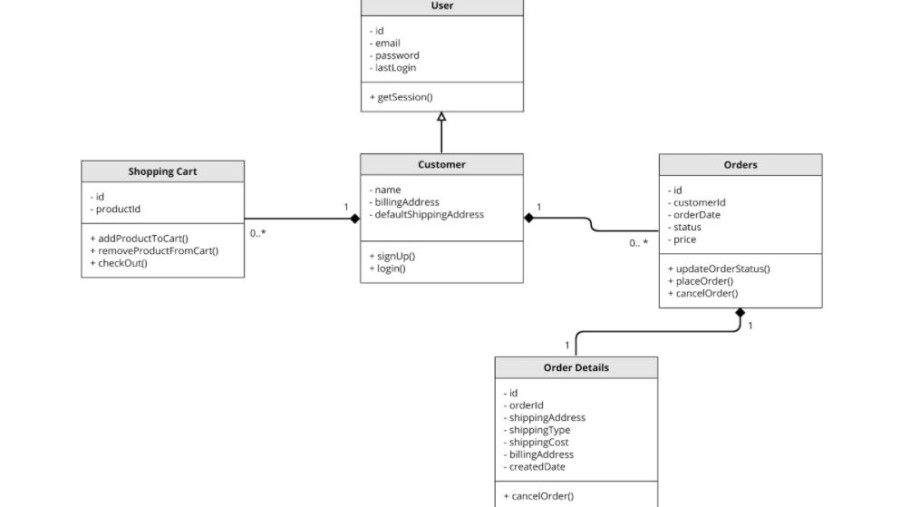
Structure diagrams display the architectural and static parts of systems. In layman’s terms, they show various objects, classes, packages, components, and more in software and their relationships. The types of UML diagrams under structure diagrams are:
Class diagramComponent diagramsObject diagramsComposite structure diagramsDeployment diagramsProfile diagramsPackage diagrams
Behavior diagrams
Behavior diagrams display the dynamic system parts or the way the software reacts to a specific input. This is used to visualize how a system interacts and behaves with users, other entities and systems, and within itself. Its types are:
Activity diagramTiming diagramState machine diagramInteraction diagramUse case diagramInteraction overview diagramSequence diagramCommunication diagrams
How does it help?
While writing code, it’s tough to track hierarchies and relationships within the software with thousands of lines of code. UML diagrams partition the software into different components and subcomponents. Also, UML diagrams were introduced when many concerns were surrounding the software development process, documentation, design, and analysis. To this, business professionals were finding a way to solve this problem with simplicity – UML. UML brought about game-changing approaches and experiments to simplify those problematic tasks. In addition, there has been an increased demand for high-quality software with reduced time-to-market and cost with the help of automation techniques. These techniques include visual programming, patterns, frameworks, and component technology. UML proposes a solution for all these problems. The benefits it provides are:
Offers users with an expressive, ready-to-use visual modeling language to exchange and develop meaningful modelsProvide independence from the specific development processes and programming languagesIt gives specialization and extensibility mechanisms to extend the key concepts.Encourages the usage of object-oriented toolsForms the basis to learn the modeling languageSupports high-level software development concepts, including collaborations, components, patterns, and frameworks.
Where is it used?
UML diagrams are used for many purposes:
In complex apps that need collaboration and effective planning from different teams and require a straightforward way of communication,Helping non-programmers understand the essential requirements, processes, and functionalities of a softwareTo enable teams to visualize user interactions, static structure, and processes effectively with diagrams and save time.Software documentation so people can easily understand all about a system.
So, this was all about UML diagrams. Now, if you are motivated enough to use them for your software, it’s time you understand HOW to do it effectively in less time. Use the power of automation and technology to reduce time in creating UML diagrams that used to be huge time-taking previously. That said, there are lots of UML diagram tools available that you can use to design the software processes, ideation, documentation, etc., efficiently. So, let’s take a look at some of the best UML diagram tools that you can consider to create exemplary diagrams and ease your software development process.
Moqups
UML diagram templates by Moqups are helpful when you create new software by providing support in the entire development journey. They also help you stay organized and always informed while keeping everyone in the loop on shared goals. While working with these templates, Moqups lets you utilize a dedicated suite of stencils to offer exclusive UML diagram support. So, check out those templates, find the one suitable for your requirements, and start building an innovative solution. You get templates for class diagrams, sequence diagrams, and use case diagrams. In addition, access various UML diagram connectors to make your diagrams more efficient and convenient to work with. Moqups provides online collaboration to facilitate real-time working with your team members irrespective of location. Remove silos from your flowcharts and diagrams; link them quickly to other digital assets like charts, mockups, graphs, and wireframes within a single Moqups project. Your team can easily create their workloads and flow along with the project by removing barriers associated with single-purpose applications.
Lucidchart
When it comes to designing, Lucidchart is a popular name, even for creating UML diagrams. It is a visual workspace combining data visualization, diagramming, and collaboration to expedite understanding and foster innovation. Lucidchart is used by technical professionals and developers to create a diagram and navigate source code, demonstrate fundamental tasks and flows, and plan new functionalities and features within the system. You can also visualize your product’s future and present state with the help of a UML graph and ensure your Agile environment is productive for data scientists, engineers, software developers, and other tech professionals. Their sequence markup editor and UML diagram-making tool make it easier and faster to learn code complexities by automating class diagram generation. You can build sequence diagrams and customize them online with ease. When you enter your markup in the dialog box popping up, Lucidchart will create a sequence diagram automatically following PlantUML standards. Or, you can also select a UML template and customize it by rearranging shapes and symbols quickly to reflect the system structure you want to portray with the UML model tool. By enabling their UML shapes library, you can get instant access to industry-grade UML shapes. Lucidchart never constraints or limits your ideas, unlike other UML tools. Whether you want to build a UML component, object, deployment, class, or package diagrams, drag and drop your chosen shapes on the canvas with no space limitations. The tool also enables you to display external interactions by positioning primary and secondary entities on the canvas like data or customers and then draw a few connecting lines for every use case. You can also create documentation to maintain your software’s sustainability and health. Lucidchart helps speed up the onboarding process, promotes effective communication of ideas, and reduces frequent meetings. It facilitates documentation and design while improving how you review, collect, and implement feedback from users and stakeholders. With real-time collaboration, you can refine UML diagrams with colleagues online, whether they use PC, Linux, or Mac. This UML diagram maker makes it easy to share your UML diagrams and customize their sharing permissions so you can invite people to review the diagrams. You can share the document through URL or email or export them to Jira, Slack, Microsoft Teams, or Confluence. Leverage the power of the presentation mode to present your diagrams or include focused sections for a detailed look at the system.
Creately
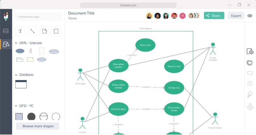
Visualize your UML diagrams with minimal effort and avail of real-time working with the documents using Creately. It helps you receive instant feedback from your clients and teams and track changes from anywhere. Utilize smart connectors and shapes, create context toolbars, and perform other advanced functionalities to draw UML diagrams easily. Creately can integrate with multiple tools you already use, such as Slack, Google Drive, Zapier, and more. You can browse thousands of high-quality and free templates drawn professionally for several use cases and scenarios. They are helpful for marketing teams, IT teams, software teams, education teams, HR teams, and others. You have access to templates for product launch flowcharts, decision-making flowcharts, workflow processes, and more. Creately is compatible with desktop (Linux, Windows, and macOS), mobile devices (iOS and Android), browsers (Chrome, Internet Explorer, Opera, Mozilla Firefox, etc.), and JIRA, Confluence, G Suite, and Chrome Web Store.
SketchBoard
The online UML tool of Sketchboard helps you create designs effortlessly and collaborate through class diagrams, use case diagrams, sequence diagrams, and more. You can create UML diagrams from anywhere. Whether you want to create UML diagrams for software documentation, mapping high-level features, or other purposes, Sketchboard works like a breeze. This UML architecture diagram software enables you to increase your team’s efficiency and creativity. Experienced software engineers have designed this tool by taking account of security and privacy as its core principles. It provides you with unlimited canvas to create any number of diagrams you like. Sharing your UML diagrams is not tough with Sketchboard. You can easily export them as PDF, PNG, SVG, and JPEG. You can also integrate Sktechboard with GitHub, Google Drive, and Slack to develop sequence diagrams, class diagrams, and others. Make UML Architecture Diagrams creation simple and leverage its collaboration features to be on the same page with the rest of the team members. You can also receive and send feedback conveniently and enhance the quality and speed of your development process. Leverage use case diagrams to draft out the system services, giving you the option to complete basic functionalities before improving your designs. It is also efficient to create class diagrams to provide a baseline for more structure diagrams. You can also create state machine diagrams to document changes in an entity’s state in different events.
Smartdraw
The powerful yet easy diagramming tool of Smartdraw is designed to make your work easy. Its intelligent formatting engine lets you create and edit your diagrams without trouble and comes with automatic spacing, color schemes, sizing, and alignment to give your designs a professional finish. Smartdraw has a broad collection of 4500+ templates and 34k+ symbols for you to choose from and implement on your diagrams. You get high-quality drawings like CAD designs with standard scales. Use the VisualScript SDK to build custom extensions or use their built-in extensions for quick designs. It helps you collaborate with your team with ease to share visuals, ideas, feedback, etc., to accelerate your development process. Smartdraw comes with enterprise-level administration and enables provisioning 1000s of users using SSO. You can integrate Smartdraw seamlessly with a tool such as MS Office, AWS, Jira, Trello, Confluence, Google apps, and more. It also works with Visio so that you can export and import diagrams without hassles.
yUML
yUML is another helpful tool you can consider to draw UML diagrams and share them with your forums, issue trackers, and wikis. It is used by thousands of authors, developers, and architects, even by professionals from giants like Twitter, AWS, and more. The tool helps you expedite diagram creation by simply typing the text without wasting hours on messy layouts. As yUML is text-based, you can create diagrams easily from your code in your CI scripts. Request images programmatically using PUT or GET commands. Tool vendors use this to extend yUML to scripts, wikis, and blogs. Create different UML diagrams that can communicate your ideas effectively without making UML technicalities a hurdle for you. yUML also takes care of security to keep your data safe and private through SSL. It grants registered users to manage diagrams within their custom namespace directly. You can also provide permalinks to your diagrams, so even if you change the diagram, the URL remains the same.
Visio
Microsoft’s Visio is a popular and easy-to-use tool that helps you make UML diagrams, solve problems, and document systems. Install this app on your desktop or access it on the web directly. They provide many pre-built shapes and templates to create advanced UML diagrams to communicate your vision while meeting industry standards such as UML 2.5. Coauthor your diagrams by sharing them across your teams to receive real-time feedback and comments on them. Demonstrate connections between different model elements by adding and modifying different relationship types such as association, dependency, and composition. In the latest Visio version, you get improved templates, including class, activity, sequence, use cases, communication, database, deployment, and state machine. You may buy Visio Professional from here.
Conclusion
UML diagrams effectively communicate your ideas, processes, functionalities, and other aspects of your software systems. Even without a programming language, you can look at UML diagrams and understand what the developer is trying to convey. Hence, choose a UML diagram-making tool to create the design that can express your innovation and take your software development process to the next level with ease and speed.

![]()


